Your access point typically is rated to produce between 14 and 21
dB (decibels) of output power. This equates to between about 25 and
100 mw (milliwatts). This is about 1 lumen or somewhat less than
one candlepower.
That's not much! by any measure. When you think about it in those
terms, it's pretty amazing that they can be used at all. Fortunately
the frequencies of light and RF are dramatically different in the way they
are absorbed and reflected by various solids.
It is good to note that metal surfaces reflect radio frequencies.
It matters little whether the metal is polished of not. The shape
of the metal surface is the critical factor. Any metal surface will
reflect radio waves. Some will work better than others.
Resonance is another property of metal surfaces. It happens when
a radio wave "bumps" into a surface that is a multiple of a quarter of a
wave length long at the frequency of the wave.
Engineers consider these properties of metal and many other factors
when designing antennas and packaging radio systems. Your access point
is a packages radio system. The engineers carefully considered not just
the type but the placement of antennas in the finished package to obtain
a desired "antenna pattern".
The FCC has mandated that you may NOT modify your access point.
If you modify the hardware (change antennas for example), you must use pre
approved antennas. Sometimes you can get these from the vendor of
your access point. Many times there are no such "approved" antennas
available.
Current solutions typically violate the integrity of the hardware
in one way or another and as a result violate existing FCC mandate.
That is not good. The fine for knowingly operating a system in violation
of FCC mandate is $5000.00 PER DAY of operation.
Our Goal:
Our goal is to use an exiting access point and without modifying the system
build a wireless bridge that can make a one mile point to point link.
We want to remain strictly legal and extend our range.
In order to accomplish this goal we will need to hit the following milestones:
Build an antenna enhancement which will not violate the integrity
of our existing system.
Build a weather proof container for our AP.
Carry power to the AP without running AC to our roof top (a decidedly
bad idea).
Move our AP out of the house and up onto the roof or side of the
building where it has clear line of site to the other end of our link.
Milestone One:
I have modeled two common access points. The WAP-11
and the DWL-1000AP.
You will discover other models for those AP's here.
That problem is solved. There are any number of ways a simple reflector
can be added to the mounting box for you AP which will yield a good reflector.
Milestone Two:
Weather proof containers can be purchased at the hardware store and if
you intend to deploy a link in a commercial or professional setting I'd recommend
you go that route. These things are UV proof and provide many other
nice features. If you are interested in saving money, here is an easy
way to do that. No doubt in your area there is a Restaurantthat serves really fine food
=). As it happens these folks have to order large quantities of seafood
and other products and quite often those products are shipped in plastic containers
*very* similar to tupperware. It is likely you will be able to obtain
several for the asking, if you are gracious enough to have a meal and complement
the cook. The ones I use are about 16 inches by 11 inches by 4 inches
and are used to ship seafood. They have a snap on cover and very much
resemble tupperware.
Your plastic box can't be sealed to be air tight. If it is you
will have condensation and heat problems. You will need to ensure there
is a 1/8" drain hole in the very bottom of the box to allow any condensation
to drip out of the box.
You will need to create vents in the side of the box which will allow
for the escape of heat but which will prevent wind blown water from entering
the container. A good way to do this is to use a small diameter plastic
pipe pushed through a hole in the side of the box and tilted downwards.
The pipe should be a minimum of 1/4" in outside diameter. Put one on either
side of the box near the top.
You will also need a port on the bottom of the box through which
your wires exit the box. You can use a bit of plastic pipe for this as well.
These wires will be one Cat-5 (the network wire) and two ten or twelve gauge
wires you use to extend the power adapter which came with the unit.
You need to make a provision for attaching the box to something on
your roof. A wall mount (high up on the side of the house is easy,
you just screw four one inch sheet rock screws through the back of the box
into the side of the house, or an eve or soffett. Mounting upon a pole
is more complex but you can purchase UV proof plastic wire ties in sixteen
to eighteen inch lengths and feed these through small slits made in the back
of the box. Be sure to seal them after mounting with silicon caulk.
You will also need to run a ground wire from the reflector screen
you will install in the box to a ground stake outside your home.
Use 10 or 12 gauge stranded copper wire to connect from the screen reflector
to the ground stake. Run this wire in as straight a path to ground
as you are able. Use a section of 8 or 10 foot copper clad grounding
rod from the hardware store for this purpose. Cut it in half and drive
it nearly all the way into the ground. Watch for underground wires
and pipes near the house. Use the other half on your friends installation
at his house. NOTE: If you want a really good ground (and really
good grounds help things a bunch) or if you have dry sandy soil, get
a section of copper plumbers pipe 5/8 inches in diameter, cut it in half and
drive it down into the ground to use as your stake. When it is installed,
mix up a cup of brine by heating four to six tablespoons of table salt in
a cup of water and pour that slowly into the pipe, all the while letting
is soak into the ground inside the pipe.
After you have made your vents and prepared the outside of your box,
you need to install the reflector(s) in the box. The links for the different
types I have tried are above. Eventually I'll have drawings of those
designs on line, but for now just cut yourself a sheet of tin foil, on quarter
inch wire mesh, or copper plumber's flashing which is 5 inches tall and
ten inches wide. Affix this to the back of the box so that you can
mount the access point above it and attach your ground wire. Make
a good mechanical attachment between the ground wire and the reflector.
If possible solder the joint. Seal the joint with silicon caulking
so that no condensation or moisture from the air can get to it.
Now you need to install a spacer block in the box. This may
well be attached through the reflector screen. No problem. This
spacer block should allow you to mount the access point so that it's antenna(s)
are centered above the reflector and between 3/4 inch and 1 and 1/4 inches
above it. Gain goes up as you near 3/4 inch but so does reflected
power, gain goes down as you approach 1 and 1/4 inches but so does reflected
power. In general one inch is just about ideal. This remains
true for any AP having dipole antennas. Both the WAP-11 and the DWL-1000AP
have dipole antennas.
Install your ether net cable.
Milestone Three:
Mount your access point to the spacer block and connect the power
cable but do not plug the power cable into the wall.
Measure off enough length on the power cable to give yourself a bit
of slack, one foot is plenty, and split the power cable down the middle.
DO NOT CUT IT YET. What you are doing is separating the two wires
from each other.
Now MARK only one of the wires with a piece of tape by wrapping
the tape completely around the wire. This is important! Getting
your wires crossed here will destroy your access point.
This bit of tape prevents you from confusing the wires. Cut through
the tape marker and the wire it wraps around so that a bit of tape remains
on each end of the cut wire. Now cut the other wire. You now
have prepared the power cable for the insertion of the extension wire(s).
Strip back the wire which is not marked with tape. Prepare
a 25 foot (but what
if I need more) piece of 10 or 12 gauge stranded copper wire (radio shack
has it) by stripping both ends. At this point make sure your wire is
running through the hole you prepared in the box for your power cable. Connect
the wire into the cable run and solder and seal with silicon caulk.
Repeat the process for the other side of the cable run, the one which you
marked with tape. You have now extended your power cable by 25 feet.
Milestone Four:
It is now time to install this puppy on the rooftop or side of your house.
This process will vary but here are some things you should think about.
Be careful on the roof. It takes a lot more energy to climb
up it that it does to fall down it. It takes even more energy to climb
up it after you have fallen down it the first time.
Don't attach the unit to a heat or electric source.
Don't install the unit near another antenna. Keep it away from
your TV, CB, or Ham radio antenna. The other end of the building looks
better.
Minimize obstructions between you and your preferred direction.
Maximize obstructions in directions you do not wish to cover. For example
I would not place an antenna on the south side of a roof if I were trying
to point at a station on the north side of the building unless I had no
other choice. Ideally I am going to place an antenna so that it is
on the nearest point of the building towards the remote station. This
allows me to place it a bit lower (usually) and actually uses the building
as an obstruction to protect me from interference from other directions.
Don't forget to seal things nice and tight when you have everything
installed. Go around the outside of the lid of the box with the silicon
caulk and seal the lid down onto the box.
Don't forget your ground wire.
Don't forget your ground wire.
Did I say, "Don't forget your ground wire?"
Do try to obtain clear line of sight to your intended coverage area.
The frequencies we are working with here are really severely absorbed by
trees and vegetation. They are blocked by buildings and other structures.
They are bent by roof edges and other structures. Ideally you are
going to be able to clearly see your area of coverage and you are not going
to be looking through a hole in the trees. Between buildings is much
better than between trees, given the same clearance.
Sometimes on really short links (less than 1/4 mile) it is possible
to bounce your link off of a water tower, metal building, or other similar
large metallic structure. This does not always work and you absolutely
must have clear line of sight from both ends of the link to the object you
are going to try to use as a reflector.
Conclusion:
I built one such system and placed it upon my roof for an afternoon of
testing. The pictures are below. I was able to very easily make
a one mile link to a laptop on the other end which had attached to it the
dish template linked elsewhere on this page. I used a DWL-1000AP as
the base unit. This unit produces about 35 mw of output power. One mile
on 35 mw is nothing to sneeze at. I believe my range estimate for this
system is conservative. I believe I will find that I am able to complete
two mile links using this system without too much trouble, so long as I am
careful in following the reflector designs linked above. When I have
time to build one of these things while a camera is handy, I will post pictures
linked to the steps above. Hopefully that won't be too long.
If anyone beats me to that, by all means send me the pics and I'll link them
in to these instructions. If you find anything in these instructions
which needs amending please let me know.
Lets have a look at the pictures.
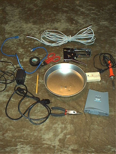
Gather your parts up. Here is a picture
of the parts I used. The first thing we will do is build a nice little wall
mount for a DWL-1000AP. In my case I am not too worried about the appearance
of this construct. I am building the unit as "proof of concept" for
another project. I am in a hurry and just want to give you the basics.
Observe the "First Rule"; "First make it work,
then make it work (fill in blank here)."
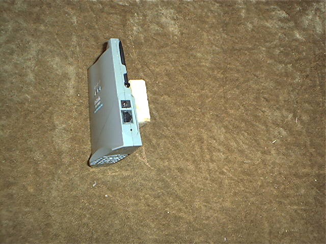
Attach the small wooden block to the back of
the DWL-1000AP. I used the screws which shipped with the AP.
Attach that assembly to a 9 inch pie tin.
I used the staple gun you see in the parts picture.
Hook up the cables and open a slot in the bottom
of the pan for the cables to run thru. This is all you need to do if
you are going to mount this AP on a wall or in a closet indoors. The
radiation pattern for this AP has been modeled. To see it click on the picture
to the right.
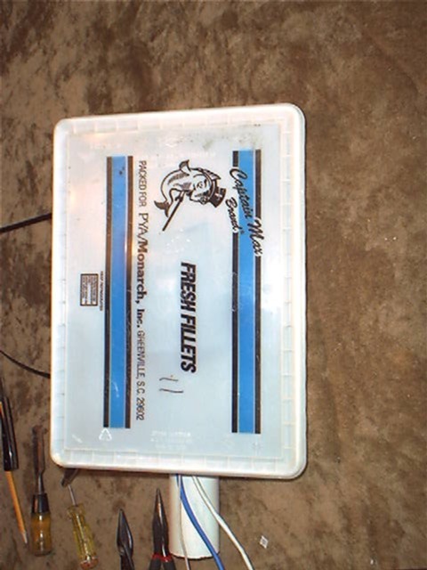
If you intend to mount the access point out
of doors, say on your roof, you will need to build an enclosure around it.
In this case I used a plastic box used to ship seafood to restaurants.
Mounting your AP out of doors is appropriate when you want to make a long
link and need to clear line of sight between a similar unit mounted remotely.
This particular AP has been tested to 2.2 miles. Testing was done using this
parabolic dish at the remote end of the link, not fresnel clean
@1MBits, and 0.9 miles with a parabolic dish at the remote end of the link,
fresnel clean @11MBits. An
easier parabolic design is here.
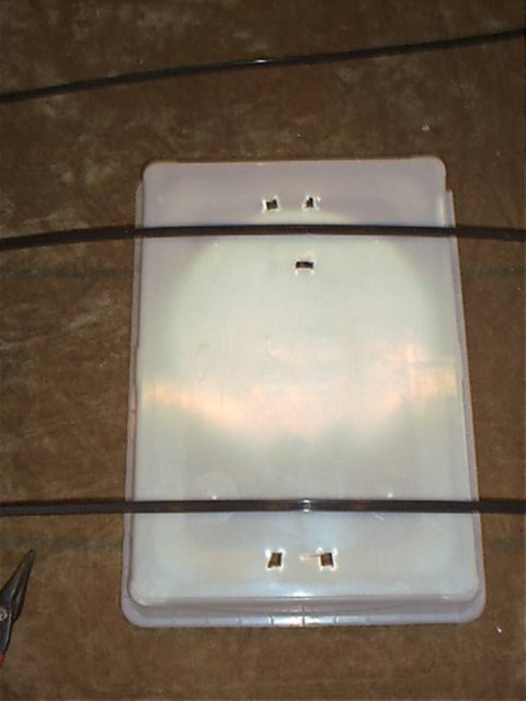
Above is the back side view of the "fish box"
as I am preparing it for the plastic wire ties I use to mount it upon a pipe
on the roof. To the right is a front view of the box with the cover
off. NOTE THE GROUND WIRE IS ATTACHED DIRECTLY TO THE PIE TIN. NOTE
YOU SHOULD HAVE ONE ON YOURS AS WELL!
Finished with the packaging. Spray paint
it a nice white or off white to help to keep the hardware cooler.
There remains the matter of the splicing
of the DC power leads to make them longer.
The pictures below show how to do that properly so that you avoid toasting
your AP.
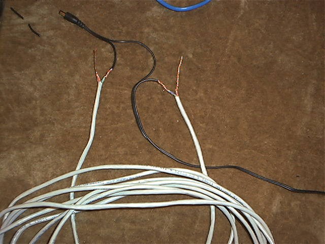
Prepare a piece of Cat-5 wire, 25' long.
Join all the solid colored wires at each end
of the cable into one wire by twisting and soldering their ends.
Now join all the striped wires at each end
of the cable by twisting and soldering their ends.
You now have a cable in your hands we can say
consists of two wire bundles, one "stripes" (striped colors) and the other
"solids" (solid colors).
Double check your work. If you get the
above wrong, you will be buying a new access point.
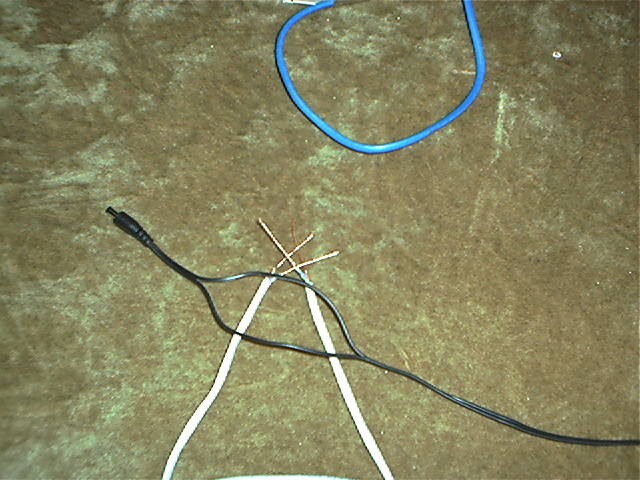
Now separate but DO NOT CUT the power cable
as shown.
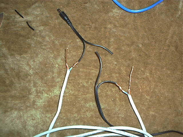
Cut ONLY ONE SIDE OF THE POWER CABLE and
splice in your Cat-5 "solids" wire. Make sure you use the bundle of
solid colored wires on each end of the Cat-5 cable.
If you get this step wrong you will be buying
a new access point.
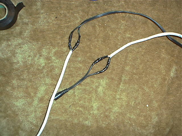
Cut the other power lead and connect in the
other half of the cat-5 . That would be the "stripes" bundle on the
Cat-5 cable.
Double check the connections to be certain
that you have made no mistakes.